Raymii.org

Quis custodiet ipsos custodes?Home | About | All pages | Cluster Status | RSS Feed
Toggling in a simple program DEC PDP-8 and PiDP-8 using the switch register
Published: 08-06-2016 | Author: Remy van Elst | Text only version of this article
❗ This post is over eight years old. It may no longer be up to date. Opinions may have changed.
Table of Contents
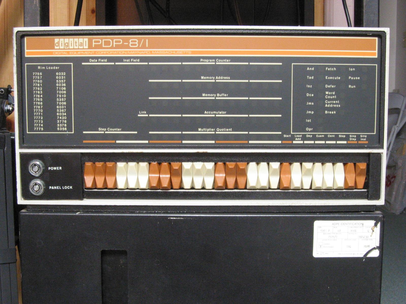
- An original PDP-8/i.
In this guide I'll show you how to toggle in a simple program on the DEC PDP-8 or the PiDP-8, or in a front-panel simulator named BlinkenBone if you lack the hardware. I have a replica of the PDP-8/I (the PiDP-8) but lacked the actual knowledge on the front panel and switches to get started and do something cool. This guide has step by step instructons, with pictures, and basic explanation. After all, what is an expensive blinking light panel without fun stuff to toggle in?
As you might know, I'm a fan of the PDP line of computers and legacy systems in general. Mainframes, homecomputers, you name it and I probably like it. Add flashing lights, panels and big controls to it and you have my attention in no time.
Plus, in previous jobs I've worked on mainframes, VAX and PDP systems and the emulators used to keep those systems running on modern hardware. Think hospitals, banks, insurance companies, train signalling control and the likes. So, the interest did not spawn from nowhere.
Oscar Vermeulen created an amazing replica of the PDP-8/I. It's a front panel with working switches and LED's, plus a simple Raspberry Pi running the SIMH emulator. I've written multiple articles on the PDP and PiDP-8 and I like the device a lot in general.
Recently I removed all Google Ads from this site due to their invasive tracking, as well as Google Analytics. Please, if you found this content useful, consider a small donation using any of the options below. It means the world to me if you show your appreciation and you'll help pay the server costs:
GitHub Sponsorship
PCBWay referral link (You get $5, I get $20 after you've placed an order)
Digital Ocea referral link ($200 credit for 60 days. Spend $25 after your credit expires and I'll get $25!)
Backstory
I did however only use the serial console and SSH to control the PDP-8 computer. Since I'm managing a lot of Linux/UNIX systems that's what I'm familiar with. But, the PiDP-8 (and the PDP-8/I) has a front panel with switches and lights. The lights show the different parts of the system, like the memory, program counter and contents of the registers and the switches allow you to manually control all those aspects.
There is little documentation on using those switches, except for the excellent manuals from DEC. No simple, get started using the switches guide. This page aims to solve that by showing you, step by step, how to toggle in a very, very simple program, by hand. What it does? It manually moves a bit through the Accumulator lamps.
I found the program and tutorial on this page, it is from the BlinkenBone author. This page is based on that, but hopefully, geared more to new users.
This guide covers the BlinkenBone panel simulator, explains the Switches, explains the Lamps (Register Indicators), explains the program and then starts with the step by step guide to toggle that in.
BlinkenBone
BlinkenBone is another super nice project which provides the front panels of
various PDP computers as a JAVA based GUI and backend server. It describes
itself as an architecture to connect simulators of vintage computers with
"Blinkenlight panels".
If you don't have a PDP-8 or PiDP-8 replica, you can use BlinkenBone to still be able to use the front panel of such an actual machine. This page has a lot of very detailed information on the PDP-8/I and it's front panel. It is a very good read.
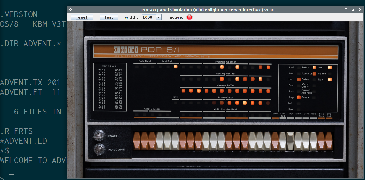
The above picture is a screenshot of BlinkenBone running on my machine showing the PDP-8/I front panel while running Adventure. I have the luck of having an actual replica, the PiDP-8, but for those without one, this is an excellent alternative.
Read this page for installation instructions on BlinkenBone. It is Java software, so it runs on Windows, Mac and Linux. There is also a special Raspberry Pi version. Installation is very easy, download the archive, extract it and run the starting script.
BlinkenBone also has a few other simulated panels, for example for the PDP-11/70, PDP-10 KI10 and a PDP-11/20. Please make some time to play with those since it's awesome.
Jorg Hoppe, behind the BlinkenBone, noted that it is an excellent idea and a great experience to run the BlinkenBone software on a large touchscreen. Quoting, "Operating the panel in original size on a 23 inch screen with your fingers is absolutely worth the extra $$$. (I use an Acer 232TL under Win10).". I did try it myself on a small Asus Transformer tablet running Windows 10, 10 inch, and even that is a very nice experience.
Switches and Lamps
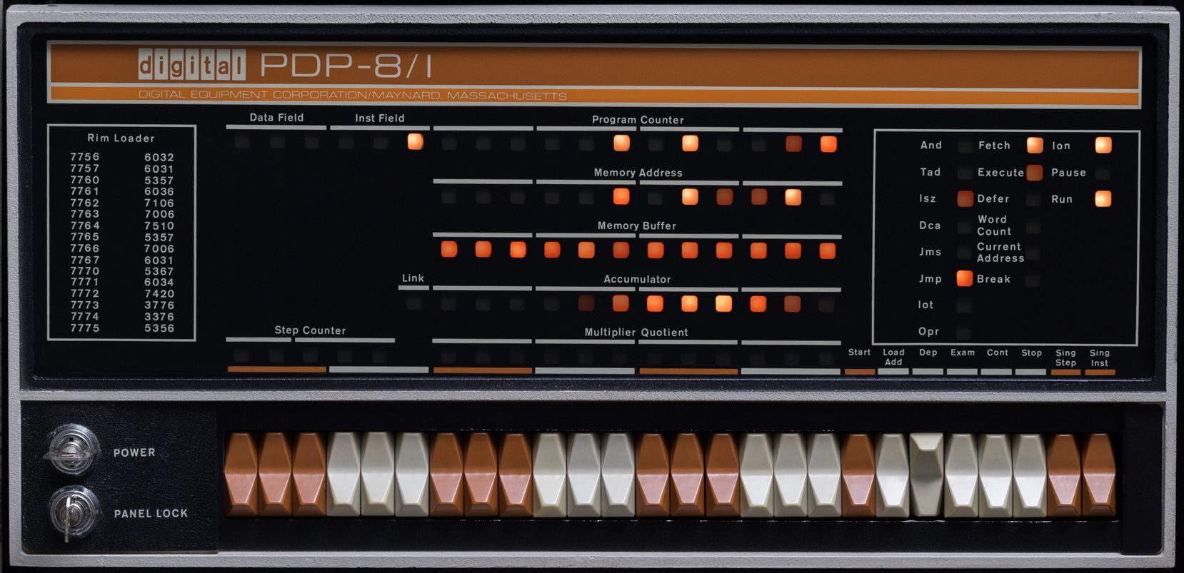
An actual PDP-8/I front panel.
I'll use the term PDP-8 further on in the tutorial, but by that I also mean the PiDP-8 or the BlinkenBone GUI.
The below sections cover the functions of the switches and the lamps. Skip over it if you just want to start toggling.
Front Panel switches
The front panel of the PDP-8/I has 26 switches. From left to right, the first
three control the Data Field (DF). DF determines the core memory field of data
storage and retrieval.
The second three control the Instruction Field (IF). IF determines the core
memory field from which instructions are to be taken.
The third, fourth, fifth and sixth pair of switches control the Switch
Register (SR). The Switch Register provides a means of manually setting a
12-bit word and load that into the PC (program counter) by pressing the Load
Add key or load the content into the MB (Memory Buffer) and core memory with
the Dep key.
The last switches are, from left to right, in order the following.
Start: Starts the program by turning off the program interrupt circuits clearing the AC (Accumulator) and L (Link), setting the Fetch state, and starts the central processor.Load Add(Load Address): This key transfers the content ofSR(Switch Register) intoPC(Program Counter), the content ofINST FIELDswitches intoIF, the content of theDATA FIELDswitches intoDF, and clears the major state flip-flops.Dep(Deposit): This key transfers the content ofSR(Switch Register) intoMB(Memory Buffer) and core memory at the address specified by the current content ofPC(Program Counter). The major state flip-flops are cleared. The contents ofPC(Program Counter) is then incremented by one to allow storing of information in sequential core memory addresses by repeated operation of theDepkey.Exam: This key transfers the content of core memory at the address specified by the content ofPC(Program Counter), into theMB(Memory Buffer). The content of thePC(Program Counter) is then incremented by one to allow examination of the contents of sequential core memory addresses by repeated operation of theExamkey. The major state flip-flop register cleared. TheMA(Memory Address) indicates the address of the data in the MB.Cont(Continue): This key sets the RUN flip-flop to continue the program in the state and instruction designated by the lighted console indicators, at the address currently specified by thePC(Program Counter) if keySS(Single Step) is not on.Stop: Causes the RUN flip-flop to be cleared at the end of the instruction in progress at the time the key is pressed.Sing Step(Single Step): This key causes the RUN flip-flop to be cleared to disable the timing circuits at the end of one cycle of operation. Thereafter, repeated operation of theContkey steps the program one cycle at a time so that the operator can observe the contents of registers in each major state.Sing Inst(Single Instructon): This key allows execution of one instruction. When the computer is started by pressing theStartorContkey, theSing Instkey causes the RUN flip-flop to be cleared at the end of the last cycle of the current instruction. Thereafter, repeated operation of theContkey steps the program one instruction at a time.
Register Indicators Lamps
The Lamps are called Register Indicators. These are also explained below, from
top to bottom.
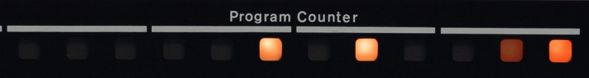
PC(Program Counter): ThePCcontains the location of the next instruction to indicators be performed.
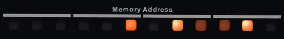
MA(Memory Address): Indicate the content ofMA. Usually, the contents ofMAindicators denote the core memory address of the word currently or previously read or written. After operation either theDeporExamkey, the contents ofMAindicate the core memory address just examined or deposited into.
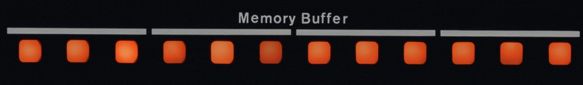
MB(Memory Buffer): Indicates the content ofMB. Usually, the contents ofMBindicators designate the word just written at the core memory address inMA.
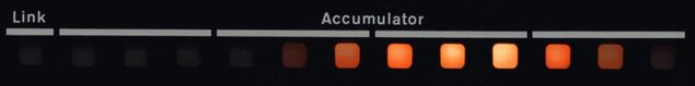
L(Link): Indicates the content ofL.AC(Accumulator): Indicates the content ofAC.
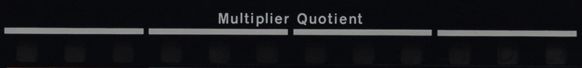
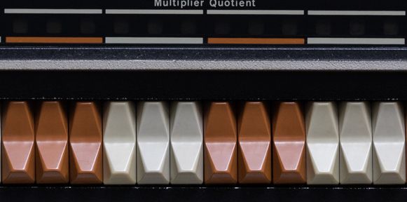
MQ(Multiplier Quotient): Indicates the content of the multiplier quotient.MQholds the multiplier at the beginning of a multiplication and holds the least-significant half of the product at the conclusion. It holds the least-significant half of the dividend at the start of division and holds the quotient at the conclusion.
Major state indicators
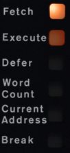
These lamps indicate that the processor is currently performing or has performed
such a cycle. Fetch for example indicates that the processor is currently
performing or has performed a Fetch cycle.
Miscellaneous indicators
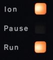
Ion: Indicates the status of theINT.ENABLEflip-flop. When lit, the interrupt control is enabled for information exchange with an I/O device.Pause: Indicates the status of thePAUSEflip-flop when lit. The PAUSE flip-flop is set for 2.75 microseconds by anyIOTinstruction that requires generation ofIOPpulses or by anyEAEinstruction that requires shifting of information.Run: Indicates the status of theRUNflip-flop. When lit, the internal timing circuits are enabled and the machine performs instructions.
Instruction indicators
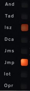
These lamps indicate that the processor is currently performing or has performed
such an instruction. For example, And indicates that the processor is
currently performing or has performed an And instruction.
The above sections were slightly adapted from this page.
The program to blink lamps
The program we are going to toggle in is a very simple program. It sets a bit in
the accumulator and HALT's. When we, the user, press the Cont switch, it
shifts the bit to the left in the AC, and so on.
We are going to use an assembler to assemble the assembly code into binary. In
this case we are using palbart. You can download palbart here and read
more on it here. In case the download site ever goes down, I've mirrored
the C code here and the linux executable here.
Below you can find the assembler code of the program:
/ shifter - manually move a bit through the Accumulator lamps
*100 / start addr
CLA CLL IAC / Link=AC=0, AC++. AC now 1
LOOP,
RAL / rotate the bit left through AC and Link
HLT / wait for user to CONTinue
JMP LOOP / again
$
There are comments in the code, and if you want to read more about the PDP-8 assembly instruction set on this page named "What is the PDP-8 instruction set?". By reading that you understand the code above a bit more.
Make sure you have downloaded palbart. Save the above code, for example in a
file named shifter.pal. Then run it through the assembler:
chmod +x ./palbart ./palbart shifter.pal
A file "shifter.lst" is produced:
/ shifter - manually move a bit through the Accumulator lamps Page 1
1 / shifter - manually move a bit through the Accumulator lamps
2
3 0100 *100 / start addr
4 00100 7301 CLA CLL IAC / Link=AC=0, AC++. AC now 1
5 LOOP,
6 00101 7004 RAL / rotate the bit left through AC and Link
7 00102 7402 HLT / wait for user to CONTinue
8 00103 5101 JMP LOOP / again
9
10 $
No detected errors
No links generated
The first collumn represents the Address and the second column represents the
(binary) Contents of that register.
Step by step
So, we have the memory addresses and the data, but how do we toggle that in?
Start by firing up your PiDP-8, PDP or start up the BlinkenBone.
After downloading and extracting BlinkenBone, navigate to that folder and, on
Ubuntu, start the prepare.sh script to install dependencies:
sudo bash prepare.sh
On other distro's, install java and rpcbind.
Start the PDP-8 with the ADVENT disk coupled:
sudo bash pdp8i_os8advent.sh
A Java window with the front panel opens, and the terminal starts up the SIMH emulator. Wait a few moments until it is finished. The terminal shows the following:
WELCOME TO ADVENTURE!! WOULD YOU LIKE INSTRUCTIONS?
>
Above is a video of a screen recording showing the front panel while ADVENT is running. If it's not loading, view it on Youtube.
Toggle!
Now on the panel (PDP-8, PiDP-8 or emulator) toggle the Stop switch. By
toggle, I mean, push it so that it changes state and push it again so that the
state is back as it was before the first toggle.
After toggling the Stop switch, the Lamps should stop moving. We've stopped
the execution of ADVENT and OS/8.
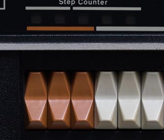
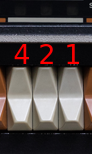
The Switch Register switches are Octal. In this case that means that they
represent 0 to 7 (8 possibilities). From left to right, a pair of three switches
represent the values 4, 2 and 1. If you toggle the rightmost switch, it
contain the value 1. If you toggle the middle switch and the rightmost switch,
it will contain the value 3 and so on. Below is a picture to make it more
clear:
Do note that the Dep switch is in the oposite position. In the pictures below
it looks like it's always toggled, and that is the case, so don't worry.
After we toggled the STOP switch, we can start toggling in the program. The
first thing we do is toggle in the value 100 and then toggle the Load Add
switch to set the start address in the PC (program counter):
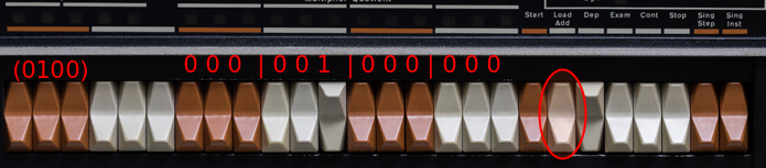
The octal value 100 is represented by the switch positions 000 001 000 000.
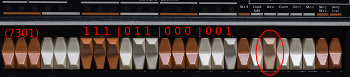
The second instruction we toggle in is 7301 (Link=AC=0, AC++. AC now 1). The
octal value on the switches it: 111 011 000 001. Do note not to toggle the
Load Add switch, but the Dep switch. I made that mistake a few times at
first. We are not loading that address, but we are depositing the value in the
address we loaded earlier. Below is a picture:
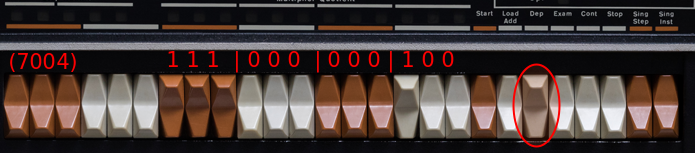
The third instruction we toggle in is 7004 (rotate the bit left through AC and
Link). The octal value is: 111 000 000 100. Picture below:
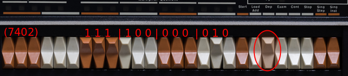
The fourth instruction is 7402 (wait for user to CONTinue). The octal value
is: 111 100 000 010. Picture below:
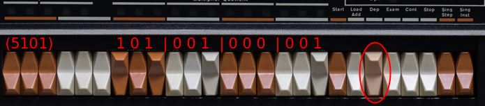
The fifth instruction is 5101 (JMP to LOOP, start over). The octal value is:
101 001 000 001. Picture below:
The sixth instruction we are toggling in is the same as the first, 0100. Toggle
the Load Add switch to set the start address in the PC (program counter):
Now the program is in the memory of the PDP. By toggling in 0100 and then loading that address, we make sure that when we toggle START, the PDP starts execution there.
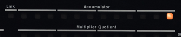
So, the next thing to do is toggle the START switch. What happens is that the
on the Accumulator lamp row, all lamps turn of and one lights up. Then nothing
happens. Toggle the Cont switch, then the Lamp turns off and the Lamp left of
it lights on. See the three examples below:
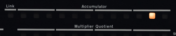
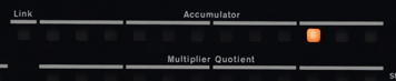
The basic flow is: set a bit, then start the loop which shifts that bit, then halts until the user toggles the continue switch.
Here below is a recording showing the emulator running this program:
If it's not loading, view it on Youtube here.
That's all there is. I hope you have enjoyed this guide and enjoyed playing with the PDP-8.
Tags: adventure , articles , dec , fortran , os-8 , pdp , pdp-8 , pidp8 , simh