Raymii.org

Quis custodiet ipsos custodes?Home | About | All pages | Cluster Status | RSS Feed
3D modeling a real world object in OpenSCAD
Published: 02-03-2014 | Author: Remy van Elst | Text only version of this article
❗ This post is over eleven years old. It may no longer be up to date. Opinions may have changed.
Table of Contents
This article shows you how I built a real world object in OpenSCAD and how I got it 3D printed. OpenSCAD is a Solid 3D modeling based on the Computational Geometry Algorithms Library. It is not like Blender, AutoCAD or Maya, who allow you to visually create and manipulate something. OpenSCAD allows you to program the entire thing. Want a cube? Type cube([10,10,10]) and you have a cube. I have no previous experience in 3D modeling or OpenSCAD, however, in about three hours I had my thing ready made.
Recently I removed all Google Ads from this site due to their invasive tracking, as well as Google Analytics. Please, if you found this content useful, consider a small donation using any of the options below. It means the world to me if you show your appreciation and you'll help pay the server costs:
GitHub Sponsorship
PCBWay referral link (You get $5, I get $20 after you've placed an order)
Digital Ocea referral link ($200 credit for 60 days. Spend $25 after your credit expires and I'll get $25!)
The Thing
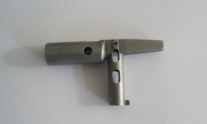
This is a key used by the Dutch Railways (NS) staff. A conductor uses it to close all the doors when a train is about to depart. They put the key in a panel like this:
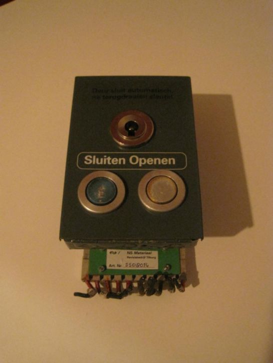
turn the key to the left which closes all the other doors, then press the blue button which closes their door and sends a signal to the train driver that he is allowed to drive away.
I've got multiple train drivers and conductors in my family so I have access to these keys. Therefore it was a nice and simple "thing" to get started with.
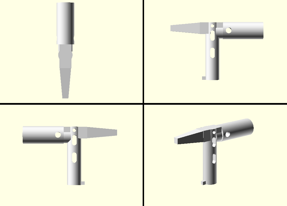
This is a picture of the end result. The full key in top, right, left and diagonal viewport.
The OpenSCAD Manual was a great help to me. The making a Thing with OpenSCAD from Hack a Day was what got me started with OpenSCAD.
The left piece
I started with the left piece because it is a very simple cylinder with a cube extruded. The radius of the cylinder is 7.5 mm, the height is 35mm.
OpenSCAD has no notice of units like centimeters, millimeters or inches. If you
define a cube([10,10,10]) you don't get a cube of 10 by 10 by 10 cm or mm, you
just get a cube of 10 by 10 by 10. It is up to the 3D printing company to decide
what those units mean. Shapeways lets you select it when you upload the model,
in the order email to my 3D printing company I state that I want the units to be
mm.
$fn=100

module left_piece() {
    difference() {
        // cylinder diameter is 15mm
        cylinder(h=35,r=7.5);
        // inner cube width and height is 9mm
        cube(size=[9,9,20], center=true );
    }
}
left_piece();
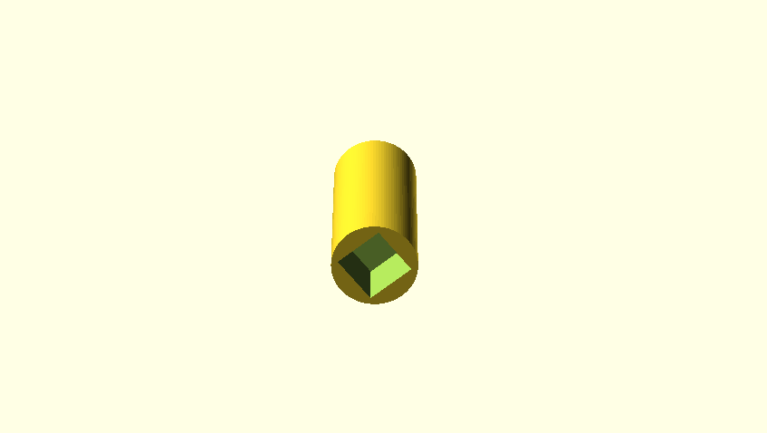
Now press F5 and see your first part of the key be created. We created a
cylinder with a height of 35 and a radius of 7.5. The difference operation, as
you might expect, substracts the cube from the cylinder, this giving us a
cylinder with a little square hole in it. As you also noticed, line comments
start with //.
The $fn=100 is the resolution of sphere and cylinder objects. Put it at the
top of your OpenSCAD document.
As you might have noticed on the photo, the left piece also has a little hole in it. This is used to put a key ring in. Lets add that hole. We'll have to to substract a small cylinder from the cylinder. However, this time we need the hole to be rotated about 90 degrees, otherwise it would be from the top to the bottom. We don't want that, we want it to go from left to right. We also want it to be a bit on top, not like the cube which is on the bottom.
We therefore use two operations, First the translate operation, which moves
objects in the 3d space by the given axis. Then the rotate operation, which
rotates objects:
module left_piece() {
    difference() {
        // cylinder diameter is 15mm
        cylinder(h=35,r=7.5);
        // inner cube width and height is 9mm
        cube([9,9,20], true );
        translate([0,15,30]) {
            rotate([90,0,0]) {
                cylinder(h=30, r=2.5);
            }
        }
    }
}

left_piece();
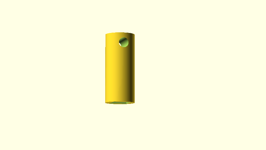
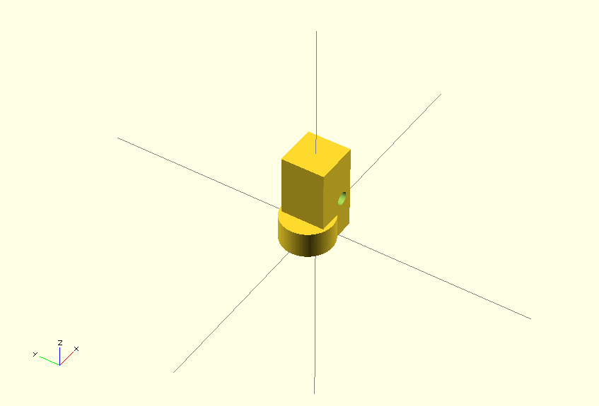
We first create a cylinder with a height of 30 (which should be more than long enough to provide a full hole in our key piece) and a radius of 2.5. This radius was measured on the original key. Then we move it by 15 on the Y-axis and by 30 on the Z-axis.
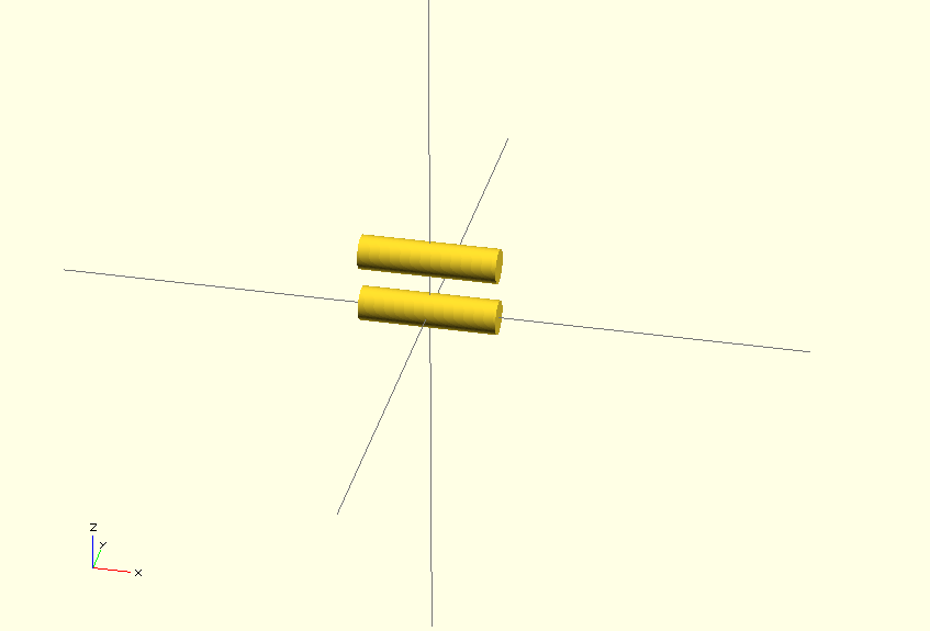
If you want to get a more visual understanding of what is happening here, try to
change the difference() operation at the top to union(). Instead of
substracting the primitives from each other, this combines all the objects. It
looks like this:
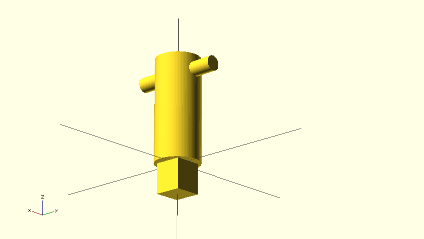
This is our full left piece right now. Leave the code up there, except for the
last line left_piece();. We are going to work on our right piece, and will put
it all together later on.
Right piece
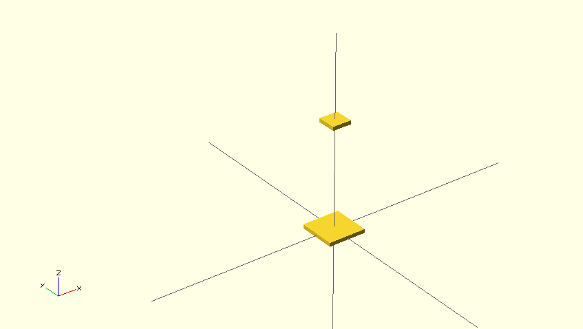
The right piece is also quite simple. OpenSCAD has the hull operation, which
combines one or more shapes together to a solid. We are going to place a small
square and a larger square and connect those together:
module right_piece(){
    hull() {
        // from heart of bottom_piece to end of right_piece = 35mm
        translate([0,0,28]) {
                cube(size=[5,5,1], center=true);
        }
        // right_piece thickness at begin right_piece is 10mm
        // right_piece thickness at end is 5mm
        cube(size=[10,10,1], center=true);
    }
}

right_piece();
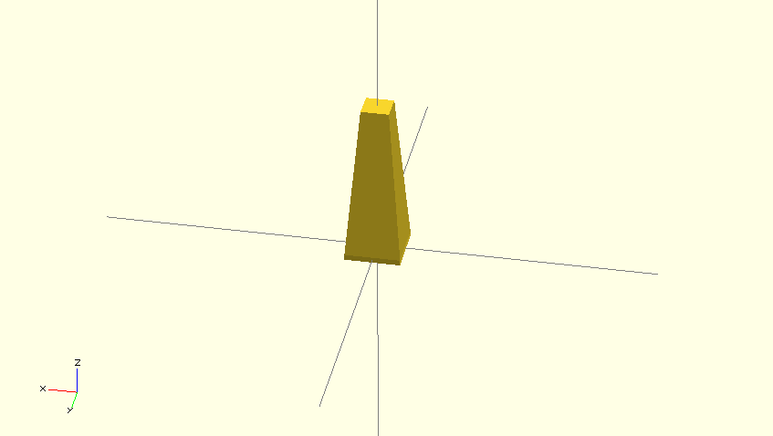
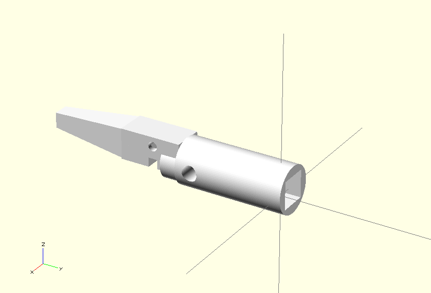
If you want to see more visually what the hull operation does, try changing it
again to union. It then looks like this:
We are done with the right piece right now. Later on we will build a connecting
piece which will hold the right, left and bottom piece together. Remove the last
right_piece(); line and move on to the bottom part.
Bottom piece
The bottom piece consists out of a few things, a cylinder with a triangle taken out. There are two large holes and one smaller hole, plus a cube at the end of the cylinder. Let's start with the cylinder and the triangle.
module bottom_piece() {
    difference() {
        cylinder(h=50,r=6);
        translate([-0,0,30]) {
            linear_extrude(height = 51, center = true, convexity = 10) {
                polygon(points=[[-4,-2],
                         [4,-2],
                         [0,5]],
                        paths=[[0,1,2]]);
            }
        }
    }
}

bottom_piece();
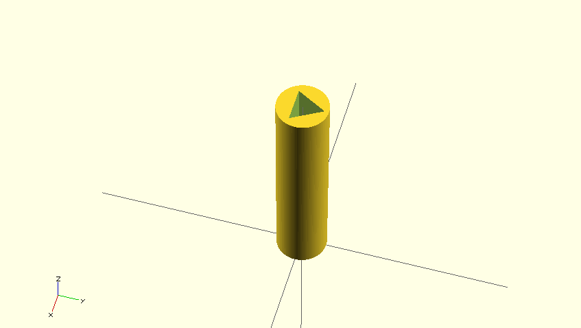
First we create a cylinder with a height of 50 and a radius of 6. We then create
a triangle using the polygon primitive. The points specify the corner points
of the triangle, which are measured up with a ruler.
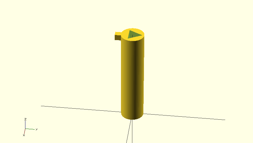
Let's add the little cube at the bottom. It does not need to be in the above
difference operation, it just needs to be placed at the bottom of the
cylinder. We'll create a small 3x4x3 cube and use translate to place it at the
bottom of the piece:
module bottom_piece() {
    difference() {
        cylinder(h=50,r1=6,r2=6);
        translate([-0,0,30]) {
            linear_extrude(height = 51, center = true, convexity = 10) {
                polygon(points=[[-4,-2],
                         [4,-2],
                         [0,5]],
                        paths=[[0,1,2]]);
            }
        }
    }
    translate([0,-7,48.5]) {
        cube(size=[3,4,3], center=true);
    }
}

bottom_piece();
We now just need to add the three holes. Because we have two of the same holes, we are going to make a module of the holes. That means we make a "solid" hole module and difference it with the cylinder.
The short_hole_in_bottom_piece is a simple cylinder rotated to the right
position:
module short_hole_in_bottom_piece() {
    translate([-6,0,5]) {
        rotate([0,90,0]) {
            cylinder(h=12,r=1.5);
        }
    }
}
You should be able to understand what we are doing in the above code by now.
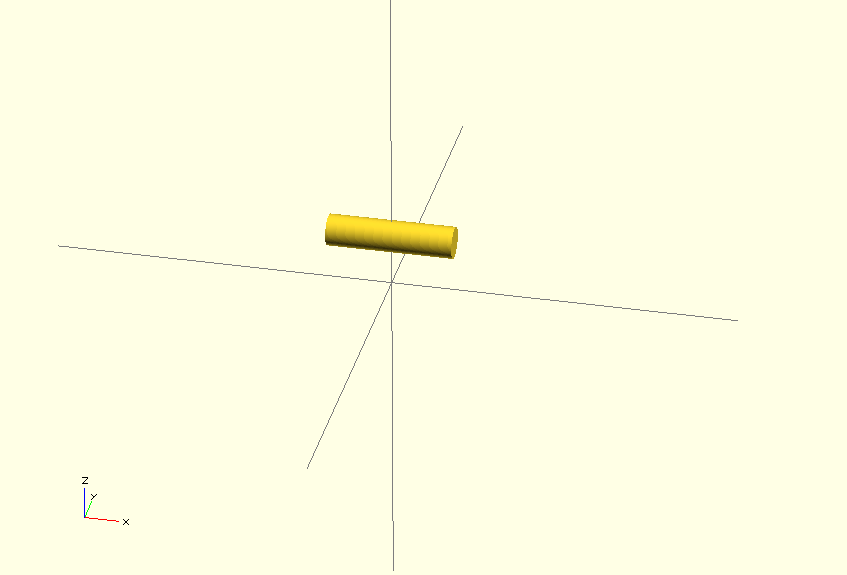
The long_hole_in_bottom_piece will consist out of two
short_hole_in_bottom_piece's with a hull operation:
module long_hole_in_bottom_piece() {
    difference() {
        translate([0,0,-5]) {
            short_hole_in_bottom_piece();
        }
        short_hole_in_bottom_piece();
    }
}
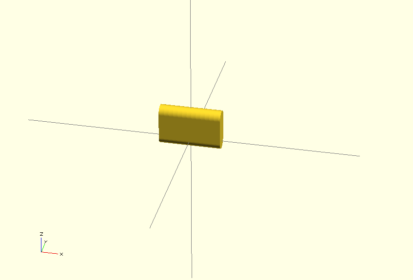
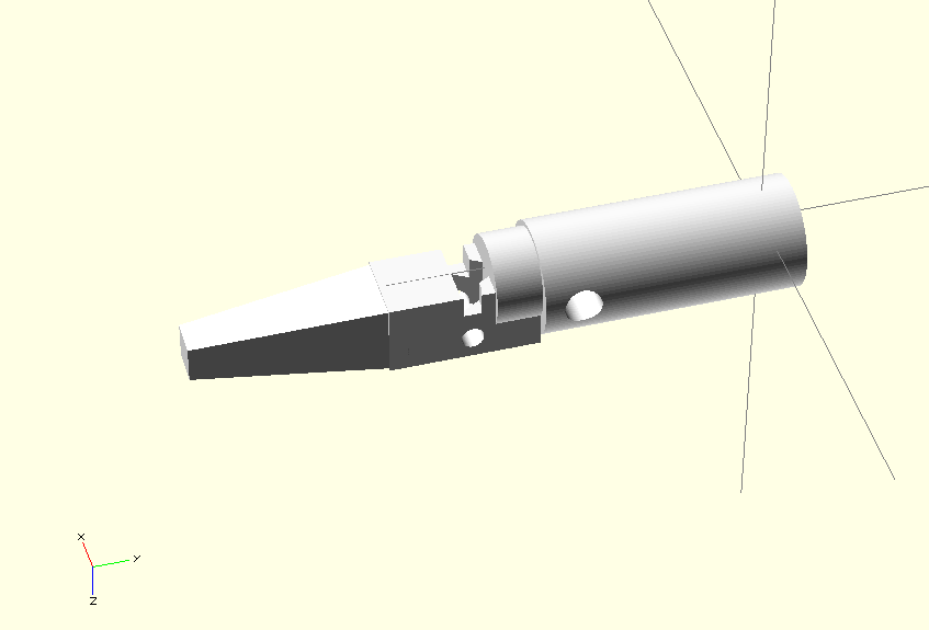
The first translate is required to place the cylinder above the other for the
hull operation. If we change the hull operation to a union like we did
before, it looks like this:
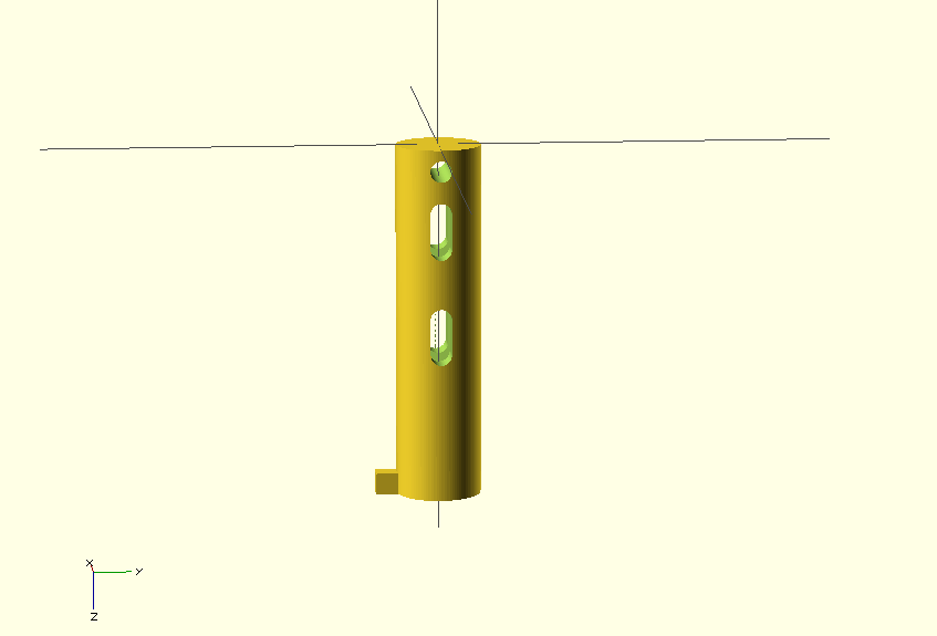
We'll use a few translate operations to place the holes in the earlier created
difference operation:
module bottom_piece() {
    difference() {
        cylinder(h=50,r1=6,r2=6);
        translate([0,0,9]) {
            long_hole_in_bottom_piece();
        }
        translate([0,0,-2]) {
            short_hole_in_bottom_piece();
        }
        translate([0,0,24]) {
            long_hole_in_bottom_piece();
        }
        translate([-0,0,30]) {
            linear_extrude(height = 51, center = true, convexity = 10)
            polygon(points=[[-4,-2],
                         [4,-2],
                         [0,5]],
                        paths=[[0,1,2]]);
            }
    }

    translate([0,-7,50-1.5]) {
        cube(size=[3,4,3], center=true );
    }
}

bottom_piece();
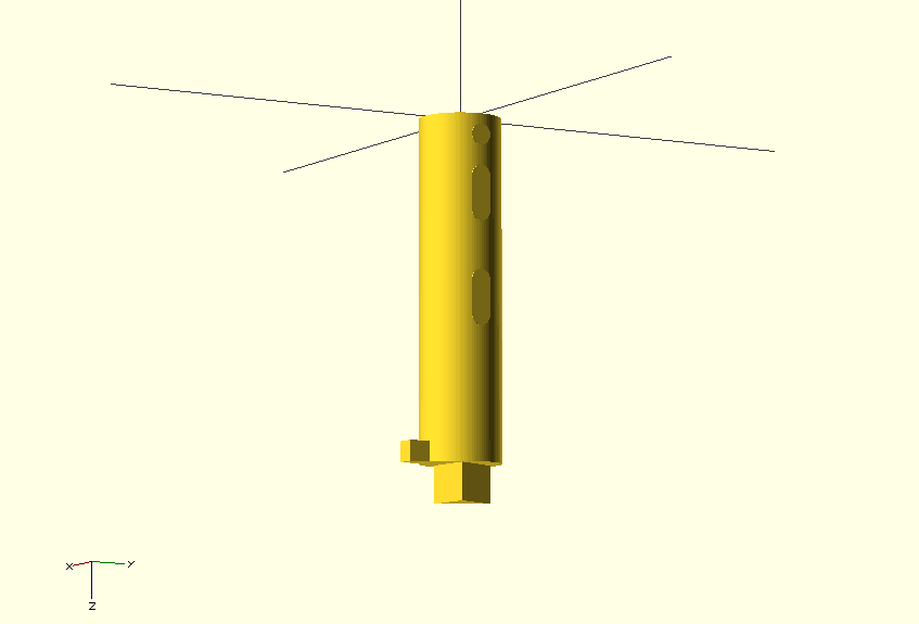
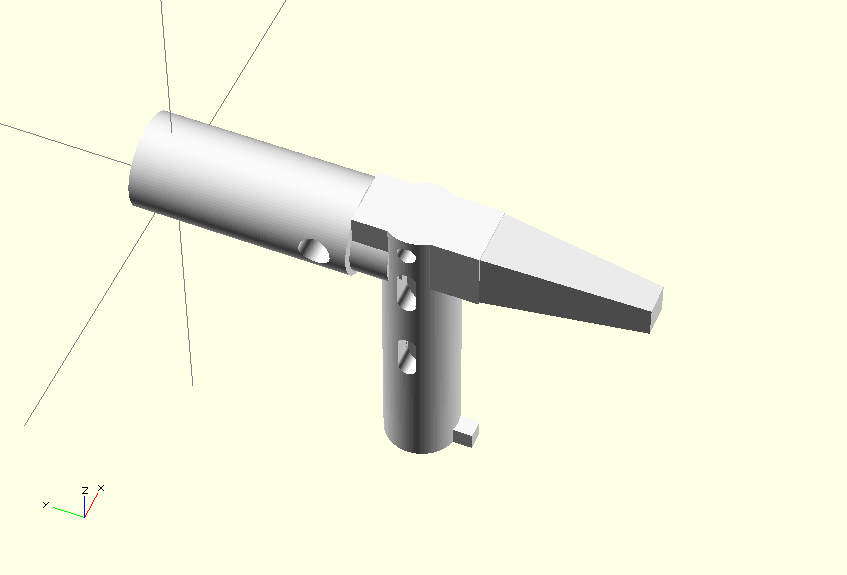
For reference, here is the same code as above with the difference replaced by
union:
Connecting piece
The connecting piece was the hardest piece to figure out and measure up. It is a
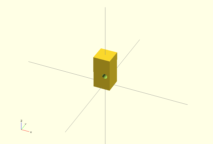
cube with a cylinder, plus a hole at the top. It also needs to match the holes
the bottom_piece has. Let's start with the cube and the cylinder hole:
module connecting_block_left_piece() {
    difference(){
        translate([0,0,9]) {
            cube([10,10,20], true);
        }
        translate([2,8,8]) {
            rotate([90]) {
                cylinder(20,1.5,1.5);
            }
        }
    }
}
The next thing we are going to add is the circle which will match the
left_piece:
module connecting_block_left_piece() {
    translate([0,0,-16]) {
        translate([-3,0,15]) {
            cylinder(h=6,r=6);
        }
    }
    difference(){
        translate([0,0,9]) {
            cube([10,10,20], true);
        }
        translate([2,8,8]) {
            rotate([90]) {
                cylinder(20,1.5,1.5);
            }
        }
    }
}
Last but not least we need to put the first long_hole_in_upper_key in this
block, otherwise it will look ugly:
module connecting_block_left_piece() {
    translate([0,0,-16]) {
        translate([-3,0,15]) {
            cylinder(h=6,r=6);
        }
    }
    difference(){
        translate([0,0,9]) {
            cube([10,10,20], true);
        }
        translate([-8,3,8]) {
            rotate([90,0,0]) {
                scale([1,1,2]) {
                    long_hole_in_bottom_piece();
                }
            }
        }
        translate([2,8,8]) {
            rotate([90]) {
                cylinder(20,1.5,1.5);
            }
        }
    }
}
That's it. It took me quite a while to get the measurements right, but a ruler is your friend in this case.
Putting it all together
We now have made four individual components of the key. We of course want to put
them all together so we have a good model. Let's start first with the upper part
of the key, connecting the left_piece, the right_piece and the
connecting_block_left_piece.
module full_upper_piece(){
    translate([3,0,-4]) {
        left_piece();
    }
    translate([5,0,32]) {
        connecting_block_left_piece();
    }
    translate([5,0,48]) {
        right_piece();
    }
}
This looks like so:
Now add the bottom_piece to the full_upper_piece:
module full_key() {
    translate([10,0,40]) {
        rotate([90,180,-90]) {
            bottom_piece();
    }
    full_upper_piece();
}
There you have your full key. Render it:
rotate([0,-90,90]) {
    full_key();
}
And you're done.
3D printing
I've let my 3D models print by Ridix in Rotterdam. They've print it on a Dimension SST 1200es with ABS+ material. This (it what they've told me) is stronger than regular ABS. The quality and especially sturdiness is very well. I've tested the key over 90 times in a panel like above, and it still works. They're very friendly and fast with printing, mostly overnight, and if you're early with sending sometimes the same day.
Tags: 3d , 3d-modeling , 3d-printer , articles , cad , openscad