Raymii.org

אֶשָּׂא עֵינַי אֶל־הֶהָרִים מֵאַיִן יָבֹא עֶזְרִֽי׃Home | About | All pages | Cluster Status | RSS Feed
SpaceCat Launchpad v2, an awesome cool little macropad
Published: 05-03-2019 | Author: Remy van Elst | Text only version of this article
❗ This post is over seven years old. It may no longer be up to date. Opinions may have changed.
Table of Contents
On Reddit, Josh (from SpaceCat) did a valentines day action, 10% off your entire order. I'm eyeing a LaunchPad for a while now, both to have a small macro pad and to experiment with QMK (firmware). So I ordered the LaunchPad full kit, an assortment of Gateron switches and a VIM keycap. This article goes over the quality, the build process and my current setup of the Launchpad.
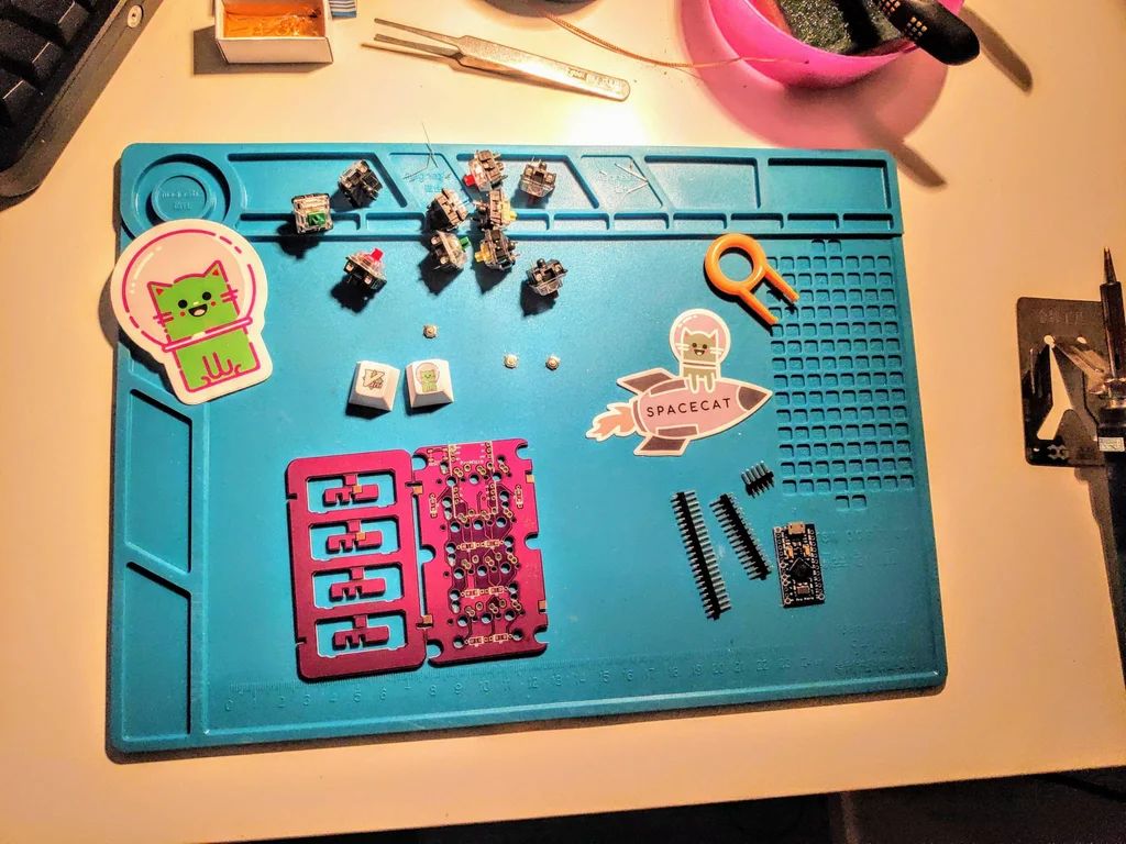
The contents of the package laid out on my soldering desk. The switches and keycaps are not included in the kit, I ordered those seperately.
The kit comes with:
- 1x Launch Pad v2 PCB
- 1x Arduino Pro Micro 5v
- 2x 12-Pin Headers
- 8x Diodes
- 1x Alps SMD Switch (reset switch for the Arduino)
- 1x High Quality "Launch Pad" Vinyl Sticker
In my case I ordered the following switches:
- 2x Gateron Blue (clicky & tactile)
- 2x Gateron Green (stiffer than blue, clicky & tactile)
- 2x Gateron Red (linear)
- 2x Gateron Yellow (stiffer than red, linear)
- 2x Gateron Brown (tactile)
The keycaps are Gateron because they are cheaper than Cherry MX. This build is a nice way for me to try out linear switches (red & yellow), the green was unknown to me and the blue and brown are my favorites. A usefull switchtester you might say. I ordered two extra switches because I know I might break one or two in the build process. (And I did break one switch so good foresight)
I also ordered this super cool VIMkeycap. That one was for my white ergodox at work, not for this Marcopad.
They threw in an extra sticker and an extra Catstrounaut keycap. The quality of these keycaps is amazing. They're thicker than the normal Ergodox DSA blank keycaps and snap on to the switch better. It takes more effort to get them off the switch tho. Very sturdy, the print is high quality and it looks cool.
The kit contained 20 diodes, 3x12 header pins and three reset switches instead of the stated quantity.
The PCB is very thick. I doubted to get a case since just the bare PCB might feel flimsy, but that is not the case. For a PCB it's very thick. The feet have solder pads (instead of hot-glueing them together), you solder them to the PCB and they snap on to the plate & PCB, so it doesn't wobble at all. Overall the quality of the PCB is amazing and sturdy, which pleasently surprised me.
Do note that to build the kit, you need to have a soldering iron, solder and preferably some other tools used in soldering (desolder, flux, sponge cleaner, desolder sucker, etc.).
The Launchpad kit can be bought here. I'm not affiliated with spacecat, I bought this kit myself, no sponsorship or anything involved.
Marco Pad?
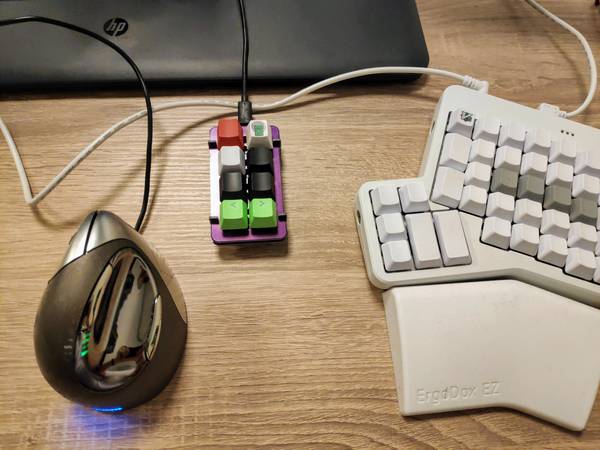
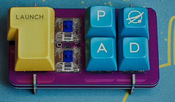
The finished Lauchpad on my desk at work, next to an Ergodox EZ and a Evonluent left handed vertical mouse.
So what is a macro pad? As you can see in the picture above, it's a small keyboard. The advantage is that you can fully program the keyboard to do anything you want. Macro pads can be small like this one, but with specific tools you can convert a normal keyboard to a macro keyboard, that's a Linus Tech Tips video. In my case I have two usecases for this macropad.
I use Jetbrains Clion a lot these days to develop C++ software. The debugger
uses specific keys as shortcuts for Step Into, Step Over and other debugging
related keys. These keys are by default mapped to F7, F8 and other Fx
keys. My current Ergodox keyboard layout does not have Function keys on the
base layer. One of the layers for the macro pad will be a debugging layer for
Jetbrains which has all the keys (plus a shift key, to start a debug build with
SHIFT+F9) to debug quickly.
The other, default layer, will have a few keys I often use during the day. Three
will be CTRL, ALT and SUPER (the windows key), right next to that will be
L. These keys are used to lock my workstation when I walk away. The other keys
will be ESC, a layer switch key and media controls (PLAY/PAUSE and SKIP).
I'm hoping to build a macro for qmk (a macro is a series of actions one key
executes) to send a CTRL+ALT+L to lock my workstation with one keypress.
These two layers will make my life a bit easier. Yes, I could program them on the Ergodox or make a special layer, but, that just isn't as clear and direct as a specific set of keys. Next to that I wanted this cute little device just because it looks so adorable and isn't hugely expensive like most mechanical keyboard things are.
Building the board
The build process for this kit is straightforward:
- Snap the board in half. One half is the PCB; the other half is the switch plate plus standoff feet
- Solder the header pins for the Arduino (on the bottom of the PCB where it says Pro Mirco)
- Solder the eight diodes (on the bottom of the PCB)
- Solder the switches (on top of the PCB. DO NOT FORGET TO PUT THE PLATE IN FIRST )
- Flash firmware to your Arduino and test it first
- Place the Arduino on the pins (this is tricky)
- Solder the Arduino to the pins
- Snap on the feet and solder them to the plate
The manual is has pictures and detailed steps to build the kit.
It took me about an hour to build the enitre kit. I did make a mistake during building, I forgot to put the plate between the switches and the PCB. That makes it a PCB mounted pad, which looks quite okay:
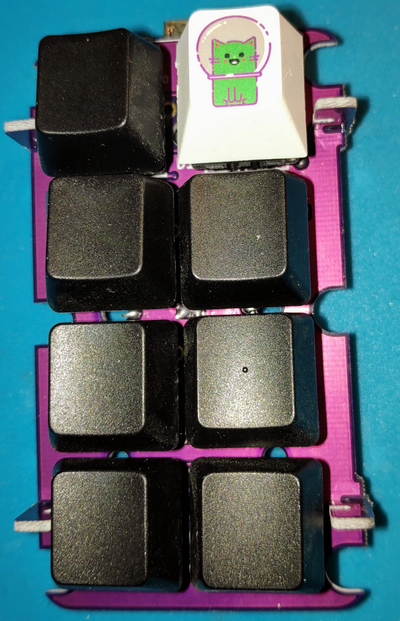
I finished the build, tested the firmware and then decided I wanted the plate in between. So, I desoldered the switches (two under the arduino are harder to desolder), broke one switch in the process and put the plate in between.
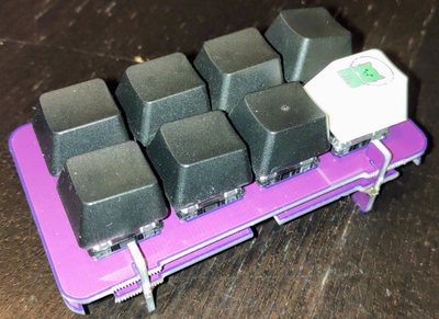
With plate it looks like this:
Some notes on the build process:
- Putting the Arduino on the header pins is a time-consuming process. It involves bending the header pins just a tiny bit and retrying. Be carefull because they can break.
- The manual did not state to put the plate between the switches first, so I forgot to do that.
- The manual does not explicitly says which side is which and on which side components go. I had to deduce it from the pictures.
- The reset switch is hard to solder correctly (mine is angled)
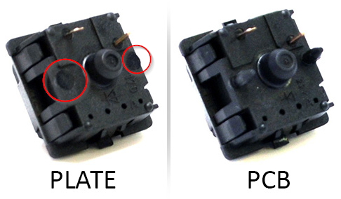
- Both PCB mount and plate mount switches work, but if you use the middle plate, you don't need PCB mounted switches.
The difference between PCB and plate mount switches are two small pins on the switch:
- The Arduino's Micro USB port sticks out. If the Arduino is moved a little bit deeper into the PCB, it wouldn't stick out. My USB port wobbles a bit so I suspect it might break off in the future. Placing it sandwiched between the Arduino and the PCB would prevent that.
This picture shows what I mean:
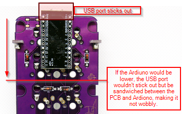
Not a huge issue for me, since I can easily desolder the Arduino and replace the USB port.
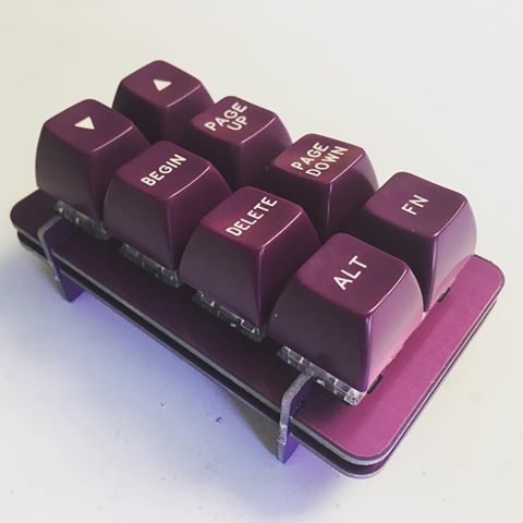
Here are three other Launchpads, not mine, but I find them to be cool. One with a case, one with matching keycaps and one with a huge ass enter key.
Launchpad with matching keycaps
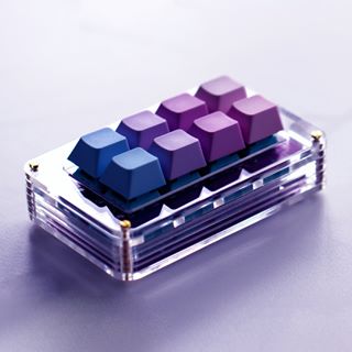
Launchpad with a clear case
Launchpad with a huge enter key
Mine is nice, plain and simple. Keycaps come from a DAS keyboard, blank SA. The green and red keycap come from a cheap set I had lying around and the Astrocat is from Spacecat.
Firmware (QMK)
The Ardiuno runs QMK, which is firmware for keyboards. It allows you to do many amazing things, supports RGB leds, layers and such. I just used the web configurator to create a basic first layout and QMK Toolbox to flash it.
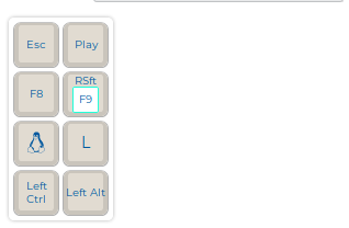
My first layout
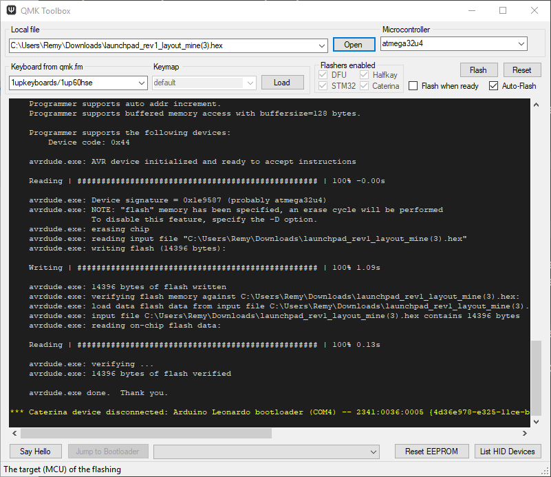
QMK toolbox flashing the layout to the Arduino
On Ubuntu I installed the Arduino IDE and used avrdude to flash the compiled
.hex file:
# install the Arduino IDE
snap install arduino-mhall119

# flash the firmware. Replace ttyACM0 with your USB port. Also replace the filename for the hex file.
/snap/arduino-mhall119/5/hardware/tools/avr/bin/avrdude -C/snap/arduino-mhall119/5/hardware/tools/avr/etc/avrdude.conf -v -patmega32u4 -cavr109 -P/dev/ttyACM0 -b57600 -D -Uflash:w:/home/remy/launchpad_rev1_layout_mine.hex
I do need to look into QMK more to program macro's and explore all other cool features for this Macro pad.
Update 2019-03-21
I've made my own keymap with QMK, see the code here.
 ,-------------------------.
 | RUN DEBUG  | RUN TARGET |
 |------------+------------|
 | STEP OVER  | STEP INTO  |
 |------------+------------|
 | STEP OUT   | RESUME     |
 |------------+------------|
 | PLAY/PAUSE | LOCK       |
 `-------------------------'
After flashing the first keymap, flashing the second and latter firmwares is harder. You need to press the reset switch twice quickly. The Arduino goes into firmware programming mode for 8 seconds. If you just press reset once, it will go into programming mode for 750 ms.
Tags: arduino , articles , electronics , ergodox , ergonomic , jetbrains , keyboard , launchpad , macropad , matias-ergo-pro , mechanical-keyboards , qmk , spacecat , split-keyboard